
How Should Buyers Evaluate ANSI B16.5 Steel Flange for Project Procurement?
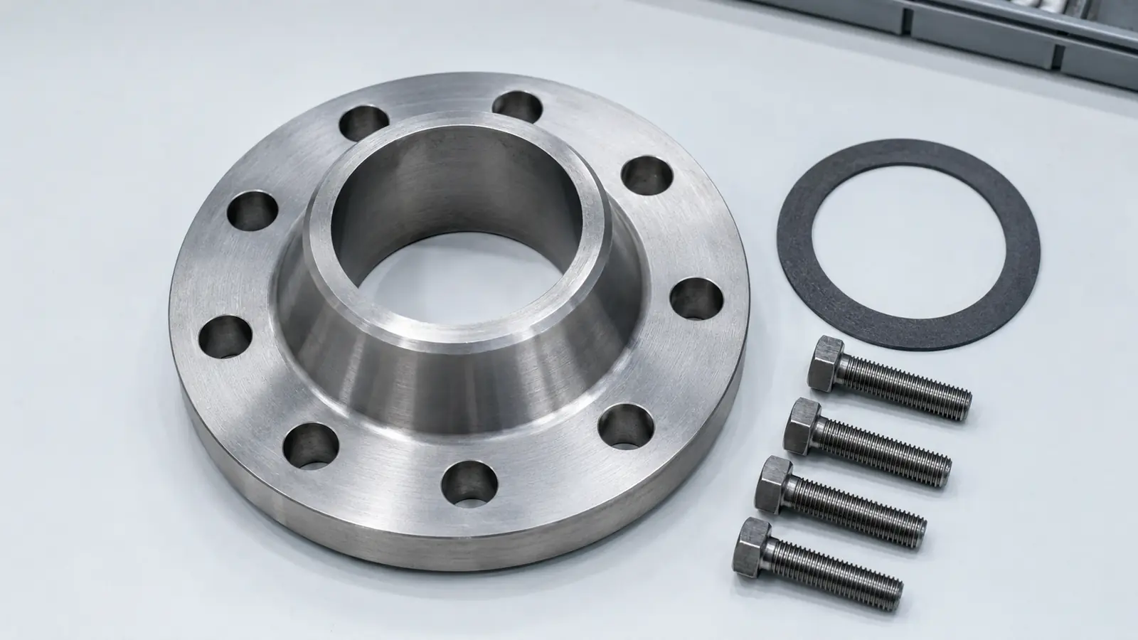
Evaluate an ANSI B16.5 steel flange in a fixed order: confirm that the flange is inside the standard’s scope, establish the required material and design temperature, verify the pressure class, select the flange type and facing, and check the bore and drilling against the pipe and mating component. Then review the gasket, bolting and assembly requirements as part of the same joint. Material certificates, approved drawings and dimensional records should prove different parts of that purchase—not be treated as interchangeable evidence.
This sequence turns a familiar product label into a project-specific connection. It also reveals why two quotations carrying the same nominal size and class can still describe different flanges.
Translate “ANSI B16.5” into the Formal Purchase Reference
“ANSI B16.5 steel flange” remains common language in searches, legacy drawings and international RFQs. The current publication is ASME B16.5-2025, Pipe Flanges and Flanged Fittings. ANSI is associated with the American national standards system, but writing “ANSI” before B16.5 does not create a separate flange specification.
The purchasing record should use the designation and edition required by the project. This matters when an owner’s piping class, equipment drawing or framework contract was developed under an earlier edition. A supplier should not update the edition silently, and a buyer should not assume that two editions are interchangeable without project review.
After that clarification, the designation should stop dominating the discussion. The useful questions are whether the item falls within the standard, what material and rating apply, how it connects, and which records will demonstrate conformity.
Reject Scope Mismatches Before Comparing Class or Price
ASME B16.5 covers pipe flanges from NPS 1/2 through NPS 24 within its stated construction and rating limits. For NPS 26 through NPS 60, ASME B16.47 provides the large-diameter steel flange framework. A larger flange is therefore not a B16.5 flange simply because its drilling resembles a familiar class pattern.
Construction is another boundary. B16.5 is limited principally to cast or forged flanges and flanged fittings, with blind flanges and certain reducing flanges permitted from plate material under the standard’s conditions. A fabricated or plate flange of another form may be suitable for a project, but it needs its actual design and dimensional basis rather than an unsupported B16.5 label.
This distinction is relevant when evaluating a large-diameter carbon steel plate slip-on flange. Size, construction method, design basis and mating details need to be confirmed directly. Treating the product as an enlarged catalogue flange can hide differences in thickness, drilling, facing and allowable service.
Scope screening should come first in the bid tab. If one offer is outside the requested standard or dimensional family, its lower price cannot be compared fairly until engineering accepts the deviation and identifies the effects on the companion joint.
Pressure Class Is a Rating Family, Not a Pressure Number
Class 150, 300, 600 and the higher class designations are not fixed allowable pressures. The standard’s pressure-temperature ratings depend on material group and temperature. Two flanges with the same class number but different materials may therefore have different rating limits at the same temperature.
The correct selection path begins with design pressure and design temperature, followed by the material permitted by the project piping class. The applicable pressure-temperature table then supports the class decision. Selecting a class from pressure alone leaves out temperature and material; selecting one only because it matches existing stock leaves out the design basis entirely.
The line specification may add conditions beyond the flange standard, such as corrosion service, low-temperature toughness or project-specific design margins. These conditions can influence the acceptable material, supplementary tests and joint configuration. A supplier quotation should return class and material together so the engineering reviewer can verify the actual rating basis.
Higher class also changes physical geometry. Thickness, outside dimensions, bolt pattern and facing details can differ. An incorrect class is not normally solved by changing the gasket at site; it may prevent the flange from mating with the equipment nozzle or companion flange.
Flange Type Determines How the Load Enters the Pipe
Weld neck, slip-on, socket-weld, threaded, lap-joint and blind flanges perform different connection functions. Maigaotuo’s flange product category organizes the relevant product family, while the piping design, fabrication method, service and maintenance strategy determine which form belongs in the purchase description. These are not cosmetic variants that a supplier can substitute on price alone.
A weld neck flange connects through a tapered hub and butt weld. Its bore and weld end need to match the adjoining pipe wall or an approved transition detail. A slip-on flange fits over the pipe and uses a different welding arrangement, so the pipe insertion and weld details become part of the fabrication review. A blind flange closes an opening and has no pipe bore to match, but it still needs the correct rating, facing and bolting interface.
The stainless steel weld neck flange page shows one product form in Maigaotuo’s range. It does not establish a universal material grade, class or bore for every application. Those items remain project inputs.
Substitution between flange types should appear as a formal deviation. Even if both alternatives share NPS and class, a change in connection method can affect welding procedure, inspection, spool length, accessibility and future maintenance.
Bore Compatibility Requires the Actual Pipe Wall
Nominal pipe size alone cannot confirm a weld neck flange bore. The adjoining pipe outside diameter may be standardized, while its internal diameter changes with wall thickness. A flange offered for one schedule can therefore create an internal mismatch when the project uses another.
The RFQ should identify the pipe standard, outside diameter and wall designation. The supplier drawing should return the flange bore, hub and weld-end geometry. For heavy-wall or unusual pipe, the project engineer may need to approve internal tapering, machining or another transition.
This is one of the most useful pre-production checks because both items may look correct on separate certificates. The pipe MTR proves pipe material results. The flange MTR proves flange material results. Neither certificate confirms that their bores align at the weld.
Equipment nozzles require the same discipline. The flange should be checked against the current nozzle drawing, including drilling, facing, projected location and any specified surface finish. “Matches Class 300” is not a complete interface confirmation.
Facing, Gasket and Bolting Form One Sealing System
A machined flange face is only one part of the pressure boundary. The facing geometry and surface condition influence gasket seating. The gasket requires a suitable compressive load. Fasteners, lubrication, tightening sequence and alignment determine how evenly that load is applied.
For this reason, raised face, flat face and ring-type joint descriptions cannot be separated from the gasket and mating flange. A ring-type joint requires matching groove geometry and a compatible ring. A raised-face joint uses a different seating arrangement. Similar outside dimensions do not make the faces interchangeable.
ASME B16.20 addresses materials, dimensions, tolerances and markings for specified metallic and semi-metallic gaskets used with referenced flange standards. ASME PCC-1 provides guidance for pressure-boundary bolted flange joint assembly within its scope. Neither document selects one universal gasket, bolting material or tightening value for every B16.5 connection. Those choices remain part of the project’s joint design and assembly procedure.
Procurement should preserve that connection between components. The flange schedule records facing and finish requirements. The gasket and bolting specifications identify the companion items. The assembly procedure controls installation. If these documents are purchased or approved independently, the final joint may be dimensionally compatible yet poorly coordinated.
Material Selection and the MTR Have Different Roles
ASME B16.5 contains material groupings for its pressure-temperature framework, but the project piping class selects the permitted material specification and grade. ASTM A105/A105M, for example, covers forged carbon steel piping components for ambient and higher-temperature pressure service. Other temperature or corrosion conditions may require other material specifications.
Material suitability is an engineering decision made before the MTR is reviewed. Once the grade is fixed, the certificate can be checked for the heat number, material designation and reported chemical or mechanical results required by the order. The heat identification on the flange should connect that physical item to the certificate.
The MTR has a narrow but important job. It does not prove bolt-circle dimensions, facing finish, flange type or bore. It also cannot show whether a machined face was damaged after inspection. Those characteristics need drawings, dimensional reports and condition checks.
A stainless steel flange likewise needs a complete grade and joint specification. “Stainless steel” identifies a material family, not a finished procurement description.
Cross-Standard Alternatives Need Mating Proof
Projects assembled across several regions may contain ASME, EN, DIN or BS flange terminology. Nominal size labels and pressure designations can look comparable while drilling, facing geometry, dimensions and material systems differ. A catalogue cross-reference is not sufficient evidence that two flanges will mate or carry the same project rating.
An offered alternative should be returned as a deviation with an interface comparison. The reviewer needs the proposed dimensions, bolt pattern, facing, gasket arrangement, material and rating basis beside the project requirement. If the substitute changes the mating flange, fasteners, gasket or site work, those consequences belong in the commercial evaluation as well.
Cross-standard substitution often appears to save money at the component level. The saving can disappear if an equipment nozzle requires an adapter, if new bolting must be sourced or if a prefabricated spool needs revision. The technical comparison should therefore extend to the complete connection, not stop at the flange unit price.
Build the Bid Tab Around Technical Differences
A useful bid tab does more than repeat “complies with B16.5.” It places the project requirement beside each supplier’s offered item and makes unconfirmed fields visible. Pricing becomes meaningful after the technical baselines are aligned.
| Evaluation field | Project input | Supplier return | Evidence before release |
|---|---|---|---|
| Scope | Standard, edition, NPS and required construction | Exact offered basis and any deviation | Data sheet and supplier drawing |
| Rating | Design pressure, temperature and material class | Material group, grade and pressure class | Engineering review against the applicable rating basis |
| Connection | Flange type, pipe wall and mating component | Bore, hub, weld end, drilling and facing | Approved interface drawing |
| Joint components | Gasket, bolting and assembly requirements | Compatible supplied or excluded components | Joint specification and assembly procedure |
| Acceptance | Material, dimensional, inspection and marking scope | Document register and inspection plan | MTR, dimensional results and traceability records |
| Delivery condition | Surface protection, packing and line-item identification | Proposed packing method | Pre-shipment condition and packing check |
A blank field should not be interpreted as compliance. It is an unresolved point. A deviation column is particularly valuable because it separates a supplier’s technical alternative from a simple omission.
Use Different Evidence at Quotation, Production and Shipment
At quotation, the supplier should return the formal standard, edition, NPS, class, type, facing, bore, material grade and document scope. This stage establishes whether the offers describe the same technical item. It is also the right time to identify exclusions such as gaskets, bolting, coating, special examination or third-party inspection.
Before production, the supplier drawing becomes the main interface record. Compare it with the piping class, pipe wall, mating flange or equipment nozzle. Additional tests and witness points should be agreed here because they may affect material allocation, manufacturing sequence and timing.
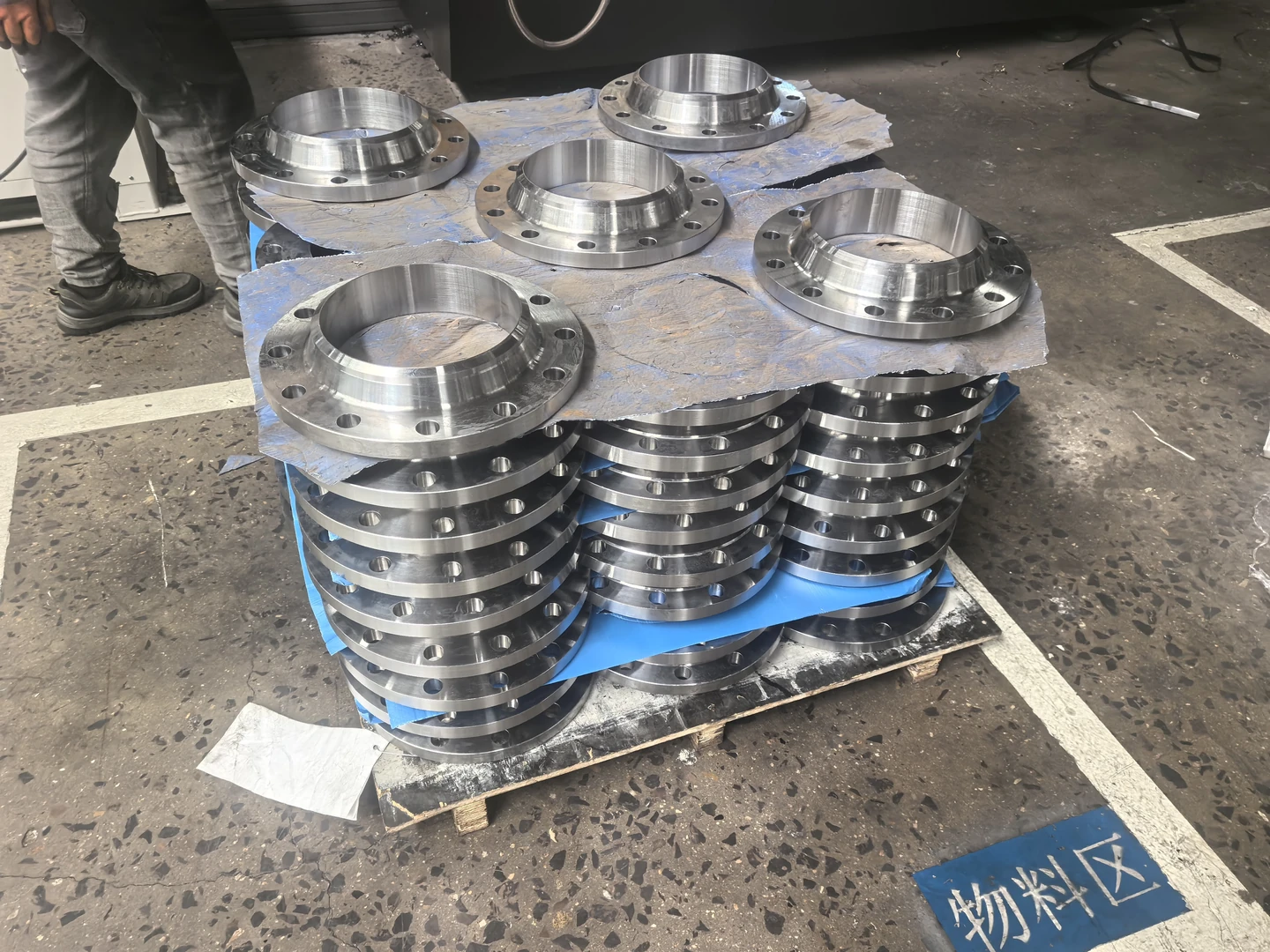
Before shipment, acceptance moves from intended configuration to physical identity. Heat marking, material documents, measured dimensions, facing condition, quantity and packing identification must all trace back to the approved line item. Protective covers or separators may be needed to keep machined faces from contacting other steel parts during transport.
Photographs can document condition and packing, but they do not replace measured results. Conversely, a complete dimensional report does not show whether the face was damaged while loading. The records work together because they answer different questions.
Know When the B16.5 Label Must Stop
The B16.5 description becomes misleading when the required size is outside the standard’s range, the construction falls outside its limitations, the mating component follows another dimensional system or the item is a project-specific design. The RFQ should then name the actual design basis and state which B16.5 provisions, if any, are still being used.
A custom flange can be the correct engineering solution. It simply needs to be quoted, reviewed and accepted as a custom item. Hiding it inside a standard line description makes scope comparison weaker and transfers unanswered design questions into production.
Close the Quotation with a Deviation Review
The inquiry package should give suppliers enough information to define the entire connection: flange schedule and quantity, governing standard and edition, design pressure and temperature, piping material class, flange type and facing, adjoining pipe wall or nozzle drawing, gasket and bolting requirements, required inspections, document scope, surface protection, packing, delivery basis and target date. These inputs allow the offered pressure class, material, bore, drilling and joint interfaces to be confirmed before commercial ranking.
Require each bidder to return the offered specification in the same field order, together with the proposed drawing and document register. The return should state whether gaskets, bolting, coating, special examination and third-party inspection are included or excluded. Any change to the requested edition, construction, material, facing, bore, dimensional family or delivery scope belongs in a visible deviation schedule with its technical and commercial effect.
The final review is not a request for a generic compliance statement. It is a comparison of resolved interfaces and declared exceptions. First remove offers that fall outside the required scope, then obtain engineering disposition for acceptable alternatives, and only then compare price and lead time across the remaining equivalent packages.
Send the completed schedule and interface documents through Maigaotuo’s technical inquiry form and request a field-by-field return. That creates a reviewable record of the offered flange, companion-item exclusions, acceptance evidence and deviations before the order is placed.